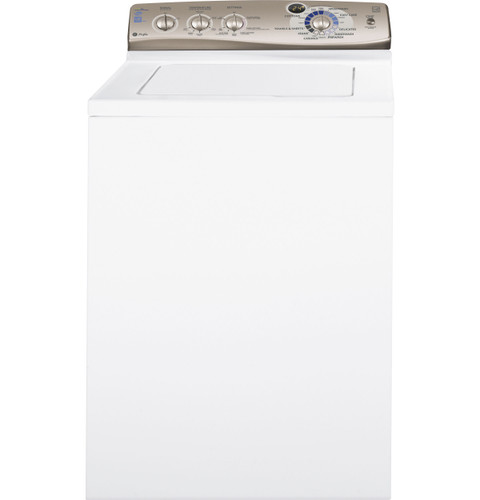
GE Profile PTWN6250M / PTWN6250MWT HydroWave Infusor washer
PTWN6250M / PTWN6250MWT: use the installation drawings to inspect setup
The Installation Instructions include diagrams for the drain-hose clamp, hot/cold rear fittings, shipping bar, electrical cord storage and clearances. These drawings help identify external installation points; they are not a service schematic and should not be used to open the cabinet or work on wiring.
Use the labels printed on the washer and follow the sheet’s numbered order. If the washer has been moved, check shipping-rod removal and hose routing before interpreting vibration or drain symptoms.
Read the shipping-bar illustration
The installation sheet says to leave packing material in the tub to support it during part of installation, then pull the shipping bar out by its yellow plastic handle after leaving at least 24 inches of clearance on the right side. Keep the bar for future moves.
If the washer was recently installed and vibrates, determine whether this exact shipping step was completed by the installer. Do not reach inside the cabinet or force a stuck part; consult the illustration or have the installer return.
Identify H and C connections
The rear connection drawing labels hot as H and cold as C. The hot hose attaches to H and cold to C, with rubber washers at hose ends; the instructions describe hand-tightening and limited additional tightening. At the household faucets, identify which is hot before connection rather than relying on a presumed left/right layout.
The illustrated strainer screens and rubber washers belong at the free hose ends when not already installed. After opening faucets, check couplings for drips. If a fitting leaks and cannot be corrected safely, shut off water and call an installer.
Follow the drain-hose restraint drawing
The drain hose is pushed into the opening on the washer’s rear and secured by clamp K and two screws L. The drawing shows the clamp position relative to the cabinet. A loose rear hose can leak or disconnect during pumping. Do not rely on a friction fit or tape in place of the shown retainer.
The installation sheet shows a supplied antisiphon clip and cable tie; use them in the locations indicated by the original instructions. Keep the household standpipe open to atmosphere and within the specified height range. Do not seal the diagrammed drain interface.
Use the clearance and leveling illustrations
The installation directions require a firm floor to minimize vibration and show the washer dimensions and service clearances. Product specification lists 27 inches wide, 42 inches high and 25½ inches deep; the space needed to raise the lid to 90 degrees is 51 inches. Ensure the lid has room to open fully and avoid placing the washer on a rug.
The product drawing is not enough to verify every installation dimension; GE directs users to consult the packed installation sheet for current dimensional data. If the floor is soft or the appliance rocks, have the installer check leveling and floor support.
Know what the drawings do not show
These documents are owner/installation literature. They do not provide a wiring diagram, component-level exploded parts view, or procedures for pump, motor, control or lid-magnet replacement. A CAD link in a product listing is not an owner repair instruction.
If service asks for a part or connection location, photograph the outside rear and label rather than removing a cover. Internal diagrams and electrical testing belong to qualified technicians.
Shipping bar or floor setup may be relevant
Check installation records and visible leveling; do not force internal parts.
Retaining clamp/screws may be loose or hose damaged
Stop use and have the connection secured per installation drawing.
Owner documents do not show component repair
Ask service for diagnosis rather than opening cabinet.